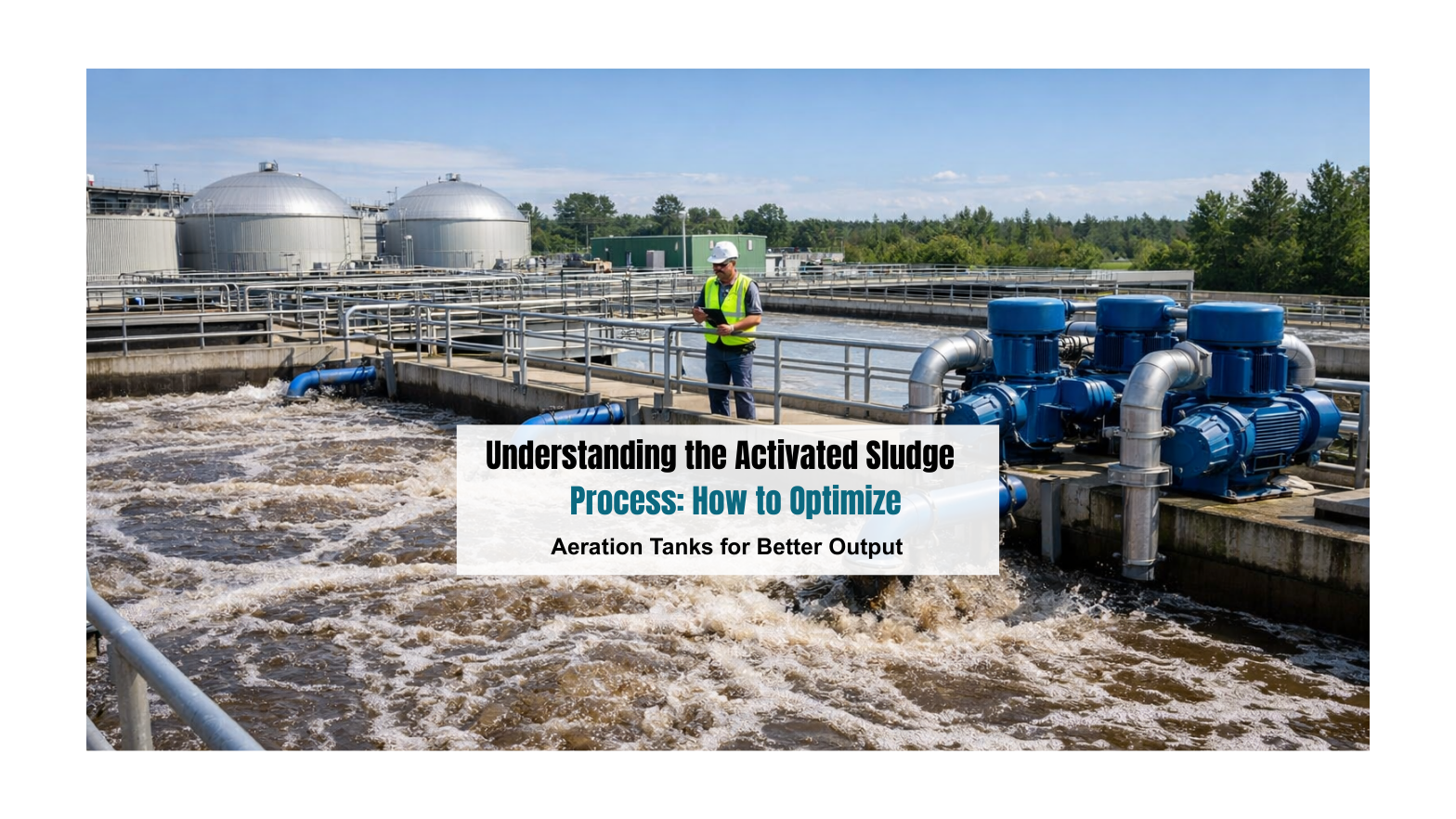
Understanding the Activated Sludge Process: How to Optimize Aeration Tanks for Better Output

The Day Your Plant Fails You And What It Actually Costs

I have stood inside enough effluent treatment plants across India to tell you this with complete confidence: the ones that fail do not fail dramatically. There is no explosion, no sudden catastrophic breakdown that gives you time to prepare. They fail quietly. A COD reading that creeps up over three weeks. A sludge blanket that starts rising a little higher in the clarifier each morning. An aeration tank that smells slightly different than it did last month.

And then one day, the SPCB inspector walks in.

If you are a factory manager in Surat’s textile corridor, or running an effluent treatment plant for a pharma unit in Hyderabad, or overseeing a food processing facility in Punjab, you already know what that moment feels like in your chest. It is not just the regulatory notice. It is the production shutdown that follows, the consent-to-operate suspension, the calls from your MD asking what went wrong, and the quiet but very real damage to your facility’s standing in the industry.

What most operations teams never figure out, until it is too late, is that the failure almost never started at the pump station or the filter press. It started in the aeration tank. Slowly, invisibly, and entirely preventably.

The aeration tank is where your entire ETP-STP plant process either earns its keep or bleeds money. And the activated sludge process that runs inside it is either your strongest compliance asset or your most expensive liability. There is rarely a middle ground.

This is a practical guide written for people who run real plants with real pressures. Not a textbook chapter. Not a vendor brochure. Just 20 years of standing next to aeration tanks across India, watching what works and what quietly destroys treatment efficiency, explained as plainly as I can manage.

The Activated Sludge Process: Why It Is the Beating Heart of Your Plant

The Activated Sludge Process: Why It Is the Beating Heart of Your Plant

Let me explain the activated sludge process the way I would standing next to your tank, not the way it appears in an engineering manual.

Imagine you have an enormous, carefully maintained community of microorganisms living in your aeration tank, billions of bacteria, protozoa, and other microscopic organisms suspended in the wastewater. These organisms are hungry. Their entire purpose is to consume the organic pollutants in your incoming effluent: the BOD, the COD, the nitrogen compounds, the suspended solids that your industry generates as a byproduct of production.

You keep them alive and active by pumping oxygen into the tank, through diffused aerators at the bottom or mechanical surface aerators, depending on your plant design. The microbes eat, multiply, and break down the pollutants. The treated water then flows into a secondary clarifier, where the microbial community, now called sludge, settles to the bottom. A portion of that settled, living sludge gets recycled back into the aeration tank to maintain the population. The excess gets wasted out of the system.

That recycled portion is the “activated” sludge. It is activated because it is biologically alive and ready to work again immediately.

Here is why this matters so much: every single stage of your sewage treatment plant or effluent treatment plant exists either to prepare wastewater for this biological stage, or to clean up after it. Your screens, your equalization tank, your primary settler, they are all just getting the influent ready for the aeration tank. Your secondary clarifier, your tertiary treatment, your disinfection system, they are all finishing what the aeration tank started.

If the biology in your aeration tank is performing at 70 percent efficiency, your downstream systems cannot compensate for that 30 percent gap. They were never designed to. This is why persistent COD exceedances in Indian industrial plants, I see this constantly in textile dyeing units, API pharma plants, and dairy processing facilities, almost always trace back to something going wrong inside the aeration tank, not at the outlet.

The aeration tank is not one component among many. It is the whole game.

STP Plant Process Step-by-Step: Moving from Primary to Tertiary Treatment

Before anyone can fully optimize an aeration tank, they need to understand one uncomfortable truth: the activated sludge process never operates in isolation. It only performs as well as the stages before it, and only delivers compliance when the stages after it are doing their job properly.

In many Indian plants, operators often focus only on blower settings inside the aeration tank while ignoring what happened twenty minutes earlier in the equalization tank or what may already be failing quietly in tertiary filtration downstream. That is like blaming the heart when the lungs are not working.

A sewage treatment plant works as a connected biological chain, not as separate civil structures built side by side.

That is exactly why understanding the full STP treatment sequence, from screening and primary settling to aeration, clarification, and final polishing, is essential before trying to improve biological performance. If you are specifically working on aeration efficiency, it also helps to first understand how the Wastewater Treatment train influences oxygen demand across every stage.

Getting Dissolved Oxygen Right, And Why “More” Is a Trap

Getting Dissolved Oxygen Right, And Why "More" Is a Trap

Here is a conversation I have had more times than I can count at plants across India:

Me: “What DO are you running at?”

Operator: “High. We keep it high to be safe.”

Me: “How high?”

Operator: “Five, sometimes six mg/L.”

Me: “And what is your monthly electricity bill?”

That conversation always ends the same way.

The belief that higher dissolved oxygen means better treatment is one of the most persistent and costly myths in industrial wastewater management in India. It feels logical, more oxygen means more active microbes, better breakdown, safer compliance margins. In practice, it means you are running your blowers harder than necessary, consuming electricity you are paying for without any treatment return, and in some cases actually disrupting the microbial floc structure that makes your sludge settle properly.

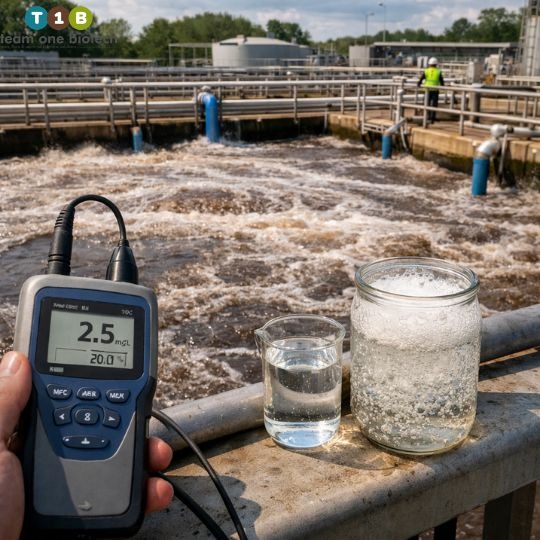
The right DO range for most industrial activated sludge systems is 1.5 to 3.0 mg/L. That is not a conservative estimate, that is the range within which your microbial community does its most efficient work. Aerobic degradation of organic matter does not require saturated oxygen conditions. It requires consistently adequate conditions.

Now flip it the other way. Drop below 0.5 mg/L and you are creating anaerobic microenvironments within the mixed liquor. That is where filamentous bacteria thrive, the organisms responsible for sludge bulking, that maddening condition where your sludge refuses to settle and starts creeping up toward your clarifier weir. If you have ever dealt with sludge bulking during peak summer production in a textile plant, you know exactly how much operational misery that creates.

What actually works in practice:

  • Stop relying on manual DO checks twice a day. Install continuous DO probes with automated blower modulation. The DO in your aeration tank changes hour by hour based on incoming load, a fixed aeration schedule set in the morning is already wrong by afternoon.
  • Walk the length of your aeration tank and map where the DO is high and where it drops. The inlet zone always has higher oxygen demand because the fresh organic load hits there first. The outlet zone often runs higher DO than necessary, which is where you can dial back aeration without any treatment impact.
  • Pay attention to seasonal shifts. During the monsoon, influent in many Indian industrial zones gets diluted, lower organic concentration, lower oxygen demand. If your blowers are still running at the same intensity they were in May, you are wasting money every single day of the rainy season.

Aeration accounts for 50 to 70 percent of total ETP energy consumption. Getting DO management right is not a fine-tuning exercise. It is one of the most significant operational cost levers you have.

MLSS: You Are Not Just Managing Sludge, You Are Managing a Living Population

MLSS: You Are Not Just Managing Sludge, You Are Managing a Living Population

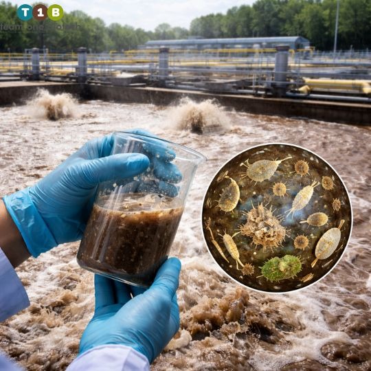
I want you to think about MLSS, Mixed Liquor Suspended Solids, differently than you probably do right now. Most plant operators think of it as a concentration reading to keep within a range. What it actually represents is the total mass of the biological workforce inside your aeration tank.

The working range for most industrial ETP-STP systems is 2,000 to 4,000 mg/L. High-strength wastewater, pharmaceutical fermentation streams, concentrated food processing effluents, may justify pushing toward 4,500 to 5,000 mg/L. But the number alone tells you less than you think.

What matters equally is the MLVSS, Mixed Liquor Volatile Suspended Solids. This is the fraction of your MLSS that is actually living, active biomass as opposed to inert mineral solids that have accumulated in the system. If your MLVSS to MLSS ratio drops below 0.6, a significant portion of what is sitting in your aeration tank is dead weight, not working biology.

I see this consistently in Indian textile plants dealing with high TDS wastewater. Elevated salinity stresses microbial cells, reduces their metabolic rate, and over time pushes up the inert fraction in the mixed liquor. The MLSS reading looks fine, 3,200 mg/L, within range, but the biology is half what it should be. The plant underperforms and no one understands why because they stopped at the MLSS number.

Sludge Age, or Sludge Retention Time (SRT), is the other parameter that most Indian plants manage poorly. Too short an SRT and you wash out the slow-growing nitrifying bacteria essential for ammonia removal. Too long and you accumulate old, tired biomass that forms pin floc, tiny, dispersed particles that do not settle cleanly in the clarifier and carry over into your treated effluent.

Controlling SRT means deliberate, calculated sludge wasting. Not wasting when the clarifier looks too full. Not wasting on a fixed weekly schedule regardless of what the biology is doing. Wasting based on actual MLVSS data, actual influent load, and a clear target SRT for your specific treatment objectives.

One more thing that is specific to Indian industrial operations: production shutdowns. Festive holidays, maintenance shutdowns, seasonal slowdowns in agro-based industries, these events starve your microbial population. When the plant restarts, operators often expect the biology to recover immediately. It does not. Natural biomass regrowth after a significant shutdown can take two to three weeks during which your plant is biologically compromised.

This is where specialized bioremediation solutions make a concrete operational difference. Team One Biotech’s microbial consortia, developed and acclimatized specifically for Indian industrial wastewater matrices, including high-TDS textile effluents, pharmaceutical process streams, and food processing loads, can cut that biological recovery window dramatically. We have seen plants that would normally take 18 days to return to stable MLSS performance after a shutdown recover in under a week with targeted inoculation. When your SPCB compliance clock is running, that difference is not academic.

The F/M Ratio: Balancing the Food Against the Workers

The Food-to-Microorganism ratio is probably the most underused process control parameter in Indian industrial wastewater plants. I say that not as a criticism but as an observation, most plant managers were never shown how to use it as a daily operational tool, so it stays in the commissioning report and is rarely calculated again.

Here is the formula, stated plainly:

F/M = (Daily BOD load entering the aeration tank) divided by (Mass of active biomass in the aeration tank)

The result tells you whether your microbial workforce is overloaded, appropriately fed, or starving. For conventional industrial ASP systems, the healthy range is typically 0.1 to 0.4 kg BOD per kg MLVSS per day.

When F/M runs too high, more food than your microbes can process, you get exactly what you would expect: incomplete treatment, elevated effluent BOD and COD, dispersed growth that does not settle. The biology is overwhelmed. When F/M runs too low, microbes with insufficient food, they enter endogenous respiration, start consuming their own cellular material, and form the fine dispersed particles that give you a turbid, poorly settling effluent.

The practical challenge in Indian industrial settings is that influent BOD is rarely stable. Batch process industries, API pharmaceutical manufacturing, distilleries, seasonal food processing, can see influent BOD swing by a factor of three or four within a single day. If your equalization tank is undersized, or is being operated at partial capacity to save pumping costs (I see this regularly), those swings hit your aeration tank directly and throw your F/M ratio into chaos.

The fix is not complicated, but it requires discipline:

  • Calculate F/M at least weekly during stable periods, and daily when your influent is variable.
  • Use your equalization tank as an active process control tool, not just a holding basin. Blend high-strength and low-strength batches intentionally before they reach the bioreactor.
  • Adjust sludge wasting to maintain your target MLVSS in response to load changes, do not wait for the clarifier to tell you something is wrong.

Hydraulic Retention Time: The Parameter That Indian Plants Most Often Get Wrong

Hydraulic Retention Time: The Parameter That Indian Plants Most Often Get Wrong

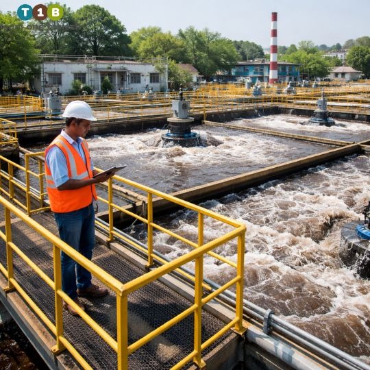
Hydraulic Retention Time, how long your wastewater actually spends inside the aeration tank, is where I see the greatest gap between what plants were designed to achieve and what they actually deliver in the field.

The textbook range for industrial ASP systems is 6 to 24 hours depending on wastewater strength and required treatment efficiency. But here is the real-world complication that no design manual adequately addresses for Indian conditions:

Indian industrial plants do not operate at steady state. They never have.

Production seasonality in agro-based industries. Power cuts that interrupt aeration mid-cycle. Festive shutdowns followed by sudden full-capacity restarts. Monsoon-driven flow spikes that push hydraulic loading well beyond design capacity. All of these compress actual HRT, sometimes to a fraction of the design value, and the wastewater that exits the aeration tank during those periods has simply not had adequate contact time with the biology.

High TDS wastewater makes this worse. Elevated salinity reduces the osmotic efficiency of microbial cells, which means their metabolic rate slows down. A microbial community treating high-TDS textile effluent needs more time to achieve the same BOD removal as one treating lower-salinity wastewater. For these applications, you should be adding 20 to 30 percent to whatever HRT your design tables suggest, and most plants in India are not doing this.

What this looks like in practice:

  • If your plant was sized for average daily flow, it is almost certainly hydraulically under-capacity for peak days. Know your peak-to-average flow ratio and design your operations around it, not the average.
  • Use inlet flow control to pace hydraulic loading during high-flow periods. Rushing wastewater through the aeration tank to keep up with production is a false economy, you will pay for it at the outlet.
  • For pharmaceutical and chemical plants treating wastewater with inhibitory compounds, do not treat HRT as a variable you adjust based on operational convenience. Certain recalcitrant compounds require a minimum contact time for biodegradation that is non-negotiable regardless of what else is happening in the plant.

Where Indian Plants Lose Efficiency Without Realizing It

After two decades of walking through ETPs and STPs across India, the losses I see most consistently are not dramatic failures. They are small, compounding inefficiencies that nobody prioritizes because the plant is technically still running:

  • Blowers on fixed timers, running at full capacity at 2 AM when the organic load is a fraction of the daytime peak.
  • MLVSS never measured, MLSS monitored in isolation, sludge quality quietly deteriorating over months.
  • Equalization tanks operating at 40 percent of capacity because someone calculated that the pumping cost was too high.
  • No biological recovery protocol after shutdowns, the plant just restarts and everyone waits and hopes.
  • High TDS not factored into aeration design, oxygen transfer efficiency assumed at standard values that simply do not apply to the actual wastewater chemistry.

If you recognize three or more of these in your plant, your aeration tank is underperforming. And your electricity bills, your chemical consumption, and your effluent quality data are all telling you so, if you know what to look for.

The Honest Case for Smarter Bioremediation

I want to be clear about something: specialized microbial inocula are not a substitute for sound process engineering. If your DO management is poor, your F/M ratio is uncontrolled, and your equalization tank is bypassed half the time, adding a microbial culture will not save you.

But when your fundamental process parameters are in reasonable shape, and you are still struggling with treatment efficiency, especially after shutdowns, during seasonal load changes, or when treating wastewater with complex or variable chemistry, a well-designed bioremediation solution is not a gimmick. It is a precision tool.

Team One Biotech has spent years developing microbial consortia that are specifically adapted to the conditions that challenge Indian industrial wastewater treatment: high TDS, high color loads in textile effluents, the inhibitory compounds in pharmaceutical streams, the fat-and-protein-rich loads in food processing facilities. These are not generic off-the-shelf cultures. They are selected and acclimatized strains that hit the ground running in your specific wastewater chemistry.

The operators who use them report faster startup after shutdowns, more stable MLSS during influent fluctuations, and measurable improvements in COD and color removal. Not dramatic overnight transformations, but consistent, reliable performance that compounds over time into real compliance margins and real cost savings.

That is the kind of result that matters when an inspector is scheduled to visit next week.

Talk to an Engineer Who Has Seen Your Problem Before

If your plant is struggling with persistent COD exceedances, sludge bulking, biological instability after shutdowns, or you are simply not confident that your aeration tank is performing at the efficiency it should be, we can help you find out exactly where the gap is.

Team One Biotech offers hands-on ETP and STP plant audits conducted by environmental engineers with direct industrial experience across India’s textile, pharma, food processing, and chemical sectors. We look at your aeration system performance, your MLSS and MLVSS data, your energy consumption relative to treatment output, and your current process control practices, and we give you a specific, prioritized action plan, not a generic report.

One Question Before You Go

Every plant has a particular operational challenge that keeps the manager up at night. For some it is sludge bulking that returns every summer. For others it is a COD number that simply will not come down no matter what they adjust. For others it is the biological crash that follows every production shutdown.

What is the single hardest operational problem you are dealing with in your aeration tank right now?

Leave it in the comments. Our engineering team reads every question and responds to each one. If your problem is common, we will address it in a future post. If it is specific to your plant, we will tell you what we would look at first.

Looking to improve your ETP/STP efficiency with the right bioculture?
Talk to our experts at Team One Biotech for customised microbial solutions.

Contact+91 8855050575

Email:  sales@teamonebiotech.com

Visit: www.teamonebiotech.com

Discover More on YouTube – Watch our latest insights & innovations!-

Connect with Us on LinkedIn – Stay updated with expert content & trends!

Thermophilic vs Mesophilic Anaerobic Wastewater Treatment in Industries

The anaerobic treatment of wastewater heavily relies on trends, and unfortunately, adaptation and innovation are very slow in progression compared to rising pollution. 

Although we are all talking about the use of AIs, sensors, IOTs, and efficient hardware, unfortunately, when we consider the industrial wastewater treatment,and broader industrial effluent treatment, we are still stuck at the same processes we were 30 years ago. If you would like to know how we are optimising wastewater treatment methods in diverse environments, feel free to connect with us today.

There needs to be a continuous update at the process level, because 99 % anaerobic plants are mesophilic, i.e, work at a temperature of 30-38 *c. In regards to biocultures for wastewater treatment, the mesophilic treatment is prominent; however, the thermophilic treatment is much more effective and compatible. 

Although it is an uncommon type of ETP water treatment, when it comes to tough-to-degrade effluents such as those with recalcitrant COD, or those with phenols, Aldehydes, etc., the thermophilic microbes treatment can be a game changer in anaerobic digestion.

This blog explores when it makes sense to shift from mesophilic to thermophilic wastewater systems, the practical advantages and challenges, and what it means for plant operators and environmental engineers.

Let us start with the basics:

Parameter Mesophilic (30–38°C) Thermophilic (50–60°C)
Microbial growth rate Moderate High
Biogas yield Moderate Higher (10–25% increase)
Pathogen kill Limited Excellent (>99%)
Energy input required Lower Higher
Process stability High Sensitive to changes
Start-up time Shorter Longer

The core of the thermophilic system lies in its high-energy fast result mechanism. The hydrolysis process is much faster, resulting in increased metabolic rate and superior pathogen control in biological wastewater treatment.

Issues where thermophilic treatment can be effective:
  1. High-Strength Industrial Wastewaters:

Effluents from industries such as dairies, food processing, slaughterhouses, distilleries and starch industries have higher levels of protiens, lipids, and polysaccharides. Thermophilic systems hydrolyze and degrade these faster, leading to:

  • Higher COD, BOD degrading efficiency.
  • Higher biogas production
  • Shorter HRT (hydraulic retention time)
  • Enhanced treatment of high-strength wastewater

2. Excess Sludge and Biomass Handling Issues:

  • While most mesophilic anaerobic systems produce higher sludge, the thermophilic system produces lower quantities of excess sludge and reduces volatile solids.

3. Strict Pathogen and Odor Control

  • The thermophilic systems give 99% pathogen elimination in STP/Centralized ETPs that handle fecal sludge or pathogen prone waste, which is crucial if:
  • Sludge is reused in agriculture
  • Water is recycled for non-potable uses
  • Especially relevant for optimized wastewater microbiome management

4. Waste Heat:

  • In case of high waste steam, condensate, or cogeneration (CHP) units, the thermal energy can be internally sourced.
  • This supports efficient energy recovery within the plant
Microbial Diversification: Fragility Meets Efficiency

In case of the microbial cultures for wastewater treatment, the thermophilic microbes are completely different from mesophilic ones. Although thermophiles are fewer but are formidable with higher metabolic abilities in the organic waste degradation.

Key Observations:

  • Thermophilic methanogens are more sensitive to pH, VFA spikes, and loading rates.
  • Shock loads (especially of fats, solvents, or salts) can cause faster crashes.
  • Granular sludge formation is more difficult at thermophilic temperatures; biofilms or hybrid systems are better suited.
Biogas enhancement: Quantitative and Qualitative

Thermophilic systems offer 10-25 % higher biogas yield per unit COD removed. More importantly, the methane content is often higher (up to 70-75%) compared to 60-65% in mesophilic digestion.

This makes the Thermophilic process enticing where:

  • On-site biogas is used for power/steam
  • Fossil fuel replacement is a business or ESG goal
  • Carbon credit mechanisms or green energy policies apply
  • Also aligns with zero liquid discharge (ZLD) and carbon neutrality efforts
Operational & Engineering Challenges in sewage treatment process

1. Temperature maintenance:

Temperature maintenance is the key of thermophilic processes, which is altogether challenging both technically and economically, especially in large tanks and in colder environments. 

2. Narrower process Window

Thermophiles work in a smaller range.  Any variation in:

  • pH (ideal: 7.2-7.6)
  • Alkalinity ratio (IA/TA < 0.3 )
  • VFA accumulation

Can lead to performance drops

3. Start-Up Lag

Thermophilic start-up can take 30-60 days, requiring:

  • Seeding with adapted sludge
  • Step-wise temperature ramping
  • High monitoring effort

4. Foaming & Scum

Due to high gas production and surfactant sensitivity, thermophilic systems foam more easily, especially during acidification.

Know the Process, Not just the Temperature:

To be precise, a thermophilic system is not for every ETP (Eluent treatment plant), however, it is effective for any ETP where it is applied. It no doubt is high energy, difficult in operations, and with fragile microbial populations, but it always outpaces mesophilic treatment in COD/BOD control, methane gas production, and cleaner sludge.

et, it’s not a plug-and-play upgrade. You must rethink your sludge management, monitoring protocols, nutrient balancing, and energy integration.

The question isn’t whether thermophilic digestion works—it’s whether your plant is ready to manage the precision and potential that comes with it.”

If you’re designing or upgrading an anaerobic system and want to make it future-proof—especially for energy recovery or zero-liquid discharge (ZLD) ambitions—don’t ignore the thermophilic path. Just walk it carefully.

Partner with Team One Biotech for expert guidance in optimizing your ETP’s aeration and biological treatment processes. Our tailored bioculture solutions and technical expertise ensure enhanced treatment efficiency in anaerobic digestion and wastewater microbiome optimization.

Learn more at www.teamonebiotech.com or reach out at sales@teamonebiotech.com/8855050575

???? Discover More on YouTube – Watch our latest insights & innovations!

???? Connect with Us on LinkedIn – Stay updated with expert content & trends!

Toxic Shockwaves Travel Through ETPs How to Deal
How Toxic Shockwaves Travel Through ETPs: A Deep Dive into Impact, Zone-Wise Failure, and Recovery

A sudden or abrupt change from regular mechanisms, schedules, habits, or play is detested everywhere, right from living to non-living beings and from nature to industries or the metropolis.  These sudden changes sometimes come with the signs of change that, if identified at the right time, either prevent or make one prepare. But not all thunders come up with lightning.

Here, as we talk about wastewater treatment in ETPs, shock loads remain one of the most common and feared issues.With the onset of shock loads or the sudden introduction of a toxic system with lethal compounds leads to complete disarray in the system, and the whole microbial population gets attacked and damaged and it a tough task to reboot it and get it back to its normal stage.

However, if we know how toxic shockwaves in ETP travel in different systems and what signs the system produces before and during the onset, we can empower us to control this unwanted phenomenon.???? Need expert support in handling or preventing toxic shockwaves in ETP? Contact our team at TeamOne Biotech for consultation, solutions, and support.

Let’s explore the shockwave travel mechanisms, early signs of warning, zone-wise failure and how to recover.

What is Toxic Shock ?

A sudden short-terms ingress of physical or chemical conditions that disrupts routine mechanisms an d disrupts microbial populations.

The Culprits: Common Toxic Agents:

  • Heavy metals (e.g., Cr⁶⁺, Zn²⁺, Cu²⁺): Inhibit enzymes and damage membranes.
  • Phenols and aromatic solvents: Disrupt cell walls, denature proteins.
  • Quaternary ammonium compounds (QACs): Destroy microbial membranes.
  • Strong acids or alkalis: Denature enzymes and destroy extracellular polymeric substances (EPS).
  • High TDS or salts: Cause osmotic shock, dehydration of microbial cells.
  • Temperature spikes: Above 40°C can be lethal to most ETP microbes.

A high COD  is not always directly proportional to toxicity. Even in a batch with COD of 2000 ppm, a 50 ppm phenol will cause disruptions.

How do toxic shockwaves in ETP travel through each zone?

1.Anaerobic Zone:

The anaerobic digestors or UASB reactors break down organics into methane or carbon dioxide by acidogenic and methanogenic bacteria.

The Effect of Toxic Shock:

Methanogens are more prone to shock as they are highly sensitive to pH shifts, metals, and aromatic solvents. A toxic load here may: 

  • Kill methanogens outright, collapsing methane production.
  • Lead to accumulation of VFAs (volatile fatty acids), crashing the pH below 6.5.
  • Result in black sludge, gas bubbles, and floating scum layers.
Indicators:

  • Drop in biogas flow rate (if monitored).
  • pH drop in digester effluent.
  • Sulphide-like odor and gas toxicity.
  • Foaming or bubbling at inlet distribution zones.
Recovery Options :

  • Stop influent flow immediately
  • Neutralize VFAs to bring pH back to 7.2 to 7.6
  • Inoculate with fresh anaerobic bioculture.
  • Feed diluted influent after 3-5 days of stabilization
2.Anoxic Zone: The Invisible Impact Zone

The function of the anoxic zone is highly dependent on nitrifying and denitrifying bacteria. 

The Effect of Toxic Shock:

Denitrifiers are facultative—more robust than methanogens—but still impacted by solvents, surfactants, and metals.

  • Nitrate remains unreduced.
  • Partial reduction leads to nitrite accumulation, which is also toxic.
  • Disruption in redox balance halts nitrogen removal.
Indicators:

  • Rising NO₃⁻ or NO₂⁻ in secondary-treated water.
  • No bubbles or gas generation from the anoxic tank surface.
  • Slight odor of chlorine or nitric oxide due to nitrite oxidation.
  • No apparent foaming or color change—this failure is usually silent.
Recovery Options :

  • Supplement the carbon source ( eg, methanol or acetate ) to restart denitrification.
  • Check and adjust DO and ORP to stay below 0.3 mg/L and -100 to -300 mV, respectively.
  • Restart mixing gently—denitrification is sensitive to turbulence.
3.Aerobic Zone: 

Aerobic microbes (heterotrophs, nitrifiers) oxidize organics and nitrogen, producing CO₂, nitrate, and water.

The effect of Toxic Shock:

It is comparatively easier to identify shocks easily in Aerobic Zones:

  • Increase in soluble COD and turbidity due to Cell lysis.
  • Release of ammonia and phosphates into the water.
  • Poor settling followed by clarifier overflows due to the disintegration of flocs.
  • Pathogen population surge due to collapsed microbial competition.
Indicators:

  • Septic-like: conditions-black, greasy foam with foul smell.
  • A sharp increase in SVI.
  • Filamentous and Nocardia become prominent.
  • Sudden DO depletion even with aeration on.
Recovery:

  • Stop the influent
  • Maintain DO at 3-4 mg/l
  • Slowly start the hydraulic load with 25-30% for the first 5-6 days and then gradually increase.
  • Waste heavily to remove lysed or decayed biomass.
  • Start adding bioculture with robust and shock-tolerant bacteria.
System-Wide Effects Ripple effects:

Secondary Clarifier:

  • Overloaded with dispersed solids → turbid effluent.
  • Sludge blanket floats or rises.
  • Polymer usage increases for sludge settling.
Sludge Dewatering:

  • Decayed biomass becomes non-dewaterable.
  • Centrifuges and belt presses clog easily.
  • Sludge has high moisture content and low calorific value.
Tertiary Treatment:

  • UF/RO membranes foul rapidly with organic colloids.
  • Sand filters choke with fine, dispersed flocs.
  • Chemical dosing (PAC, alum) surges.
Recovery Timeline Framework

PhaseActionTypical Duration
Initial ArrestStop feeding, start aeration, dose buffers0–24 hours
StabilizationAdd bio-culture, monitor parameters1–3 days
Gradual LoadingResume with diluted or treated influent4–7 days
Full RecoveryReturn to design load with full microbial function7–15 days
Conclusion:

AN ETP is like a living ecosystem with uncertainties. If we can find our early warning signs, we can prevent the discrepancies arising due to toxic shock waves in ETP. Although it is a very tough scenario to tackle but if prevented in time, the chances of vulnerability become very less. 

???? Facing recurring issues or need expert intervention? Reach out to TeamOne Biotech — your partners in effective wastewater treatment and process recovery.

???? Email: sales@teamonebiotech.com

???? Visit: www.teamonebiotech.com

???? Discover More on YouTube – Watch our latest insights & innovations!

???? Connect with Us on LinkedIn – Stay updated with expert content & trends!

Oxygen Transfer Efficiency in wastewater treatment
Oxygen Transfer Efficiency vs. Real-World Conditions: The Hidden Impacts of Diffuser Fouling and Uneven Airflow

In the world of wastewater treatment, Oxygen Transfer Efficiency (OTE) is a critical performance indicator, especially in biological treatment systems where aerobic microorganisms drive the breakdown of organic matter. On paper, system designs often promise high standard oxygen transfer efficiency based on clean-water testing. But in real-world conditions, actual oxygen transfer often falls significantly short — and two often-overlooked culprits are diffuser fouling and uneven airflow distribution.

At Team One Biotech, we help ETPs and STPs uncover these hidden inefficiencies. Contact us today to audit and improve your aeration system’s real-world performance.

Understanding Oxygen Transfer Efficiency

OTE is the percentage of oxygen from the air that actually dissolves into the wastewater. Higher efficiency means better microbial activity, lower energy costs, and more effective treatment. Bottom diffused aeration systems, particularly those with fine bubble diffuser oxygen transfer efficiency, are widely used due to their ability to maximize surface area and minimize energy use.

However, clean-water testing used to estimate standard OTE doesn’t reflect operational realities like biofilm buildup, particulate matter, or operational inconsistencies.

The Silent Saboteur: Diffuser Fouling

Over time, aeration diffusers — especially fine-pore ones — become clogged with biofilms, sludge solids, and inorganic scaling. This fouling:

  • Increases air resistance, reducing overall airflow.
  • Causes larger bubbles, decreasing oxygen transfer surface area.
  • Leads to non-uniform oxygen distribution, harming microbial populations in under-aerated zones.

As a result, a system that once transferred oxygen at 30% efficiency might drop to 15–20%, doubling the energy requirement for the same biological load.

???? Poor sludge management can accelerate diffuser fouling, leading to cascading operational issues.

Tip: Regular diffuser inspection, cleaning schedules, and selecting fouling-resistant materials (e.g., PTFE-coated membranes) can mitigate this loss.

Uneven Airflow: An Invisible Imbalance

Even with clean diffusers, uneven airflow distribution due to pipe layout, blower inconsistency, or back pressure variations can cause:

  • Overaeration in some zones (wasted energy, poor floc formation),
  • Underaeration in others (anaerobic pockets, filamentous growth, odor issues).

This imbalance affects overall oxygen transfer efficiency and biological performance, especially in large or compartmentalized aeration tanks.

The Cost of Ignoring Reality

Ignoring these issues doesn’t just degrade standard OTE — it impacts the entire secondary system:

  • Reduced MLSS activity due to low DO,
  • Increased sludge production from partial degradation,
  • Higher energy bills with little performance gain,
  • Poor compliance with discharge norms due to high BOD/COD.
Real-World Solutions
  1. Flow Balancing: Use air flow meters and control valves to ensure uniform distribution.
  2. Blower Management: VFD-controlled blowers can respond to real-time DO demands, reducing peaks and troughs.
  3. Smart Monitoring: Modern SCADA systems and DO sensors help identify zones of concern early.
  4. Preventive Maintenance: Scheduled diffuser cleaning and aeration audits pay off in energy savings and treatment reliability.
Final Thoughts

It’s time the industry moves beyond theoretical OTE and embraces a “Reality-Based Aeration Strategy”. Understanding and addressing diffuser fouling and uneven airflow are essential for sustainable wastewater treatment — both environmentally and economically.

At Team One Biotech, we specialize in supporting ETPs and STPs in optimizing their biological systems, including audits that uncover hidden losses in aeration efficiency. Let’s not just treat wastewater — let’s treat it wisely.

Reach out to us today to make sure your system isn’t silently losing efficiency — and money.

???? Email: sales@teamonebiotech.com

???? Visit: www.teamonebiotech.com

???? Discover More on YouTube – Watch our latest insights & innovations!-

???? Connect with Us on LinkedIn – Stay updated with expert content & trends!

Implementation of SBR system in a CETP
Implementation of SBR System in a CETP with T1B Aerobio Bioculture
Introduction: 

The SBR system in a CETP situated in Rajasthan handles effluents from over 40 industries in the RIICO sector the system faces difficulty in handling the load of COD above 2000 PPM, owing to discharges from textiles and  chemicals. The SBR system with 4 biological tanks and 4 cycles a day was struggling with its efficiency in terms  of COD reduction, due to which the outlet COD was very high and the load was carried on to the RO, leading to  damage of membranes and high OPEX. Contact us today to learn how we can help optimize your industrial effluent treatment plant (ETP) with customized bioaugmentation solutions.

ETP details: 

The industry had primary treatment, biological treatment, and then a tertiary treatment. 

Flow (current)  2 MLD
Type of process  SBR
No. of aeration tanks  4
Capacity of aeration tanks  3 MLD each
Total cycles in 24 hrs  4
Duration of fill and Aeration cycle  1.5 hrs and 2.5 hrs respectively
Challenges:
Parameters  Avg. Inlet parameters(PPM)  Avg. Outlet parameters(PPM)
COD  3000  800
BOD  1800  280-300
TDS  3000  1200
Operational Challenges: 
  • The primary treatment was working at 5 % efficiency in terms of COD reduction 
  • The whole SBR system was lagging in COD degradation efficiency and sustainability of MLVSS as well. 
  • The Carryover COD and unsettled biomass was traveling to RO, damaging membranes. 
The Approach: 

The agency operating the SBR system in a CETP approached us to solve their current issues.  

We adopted a 3D approach that included : 

  1. Research/Scrutiny :  
  • Our team visited their facility during the winter season as they encountered many issues at that  

         time. Team scrutinized every aspect of the plant to analyze the efficiency of each element. 

  • The visit gave us a complete idea of their processes, current efficiency, trends, and our scope of  

         work.  

  1. Analysis : 
  • We analyzed the previous 6-month cumulative data of their ETP to see trends in the inlet-outlet  

         parameters’ variations and the permutation combinations related to it. 

  1. Innovation :  
  • After the research and analysis our team curated customized products and their dosing schedules  with formulation keeping in mind the plan of action to get the desired results. This process is            called  bioaugmentation. 
Desired Outcomes : 
  1. Reduction of COD/BOD thereby improving the efficiency of biological tanks. 
  2. Degradation of tough-to-degrade effluents and develop robust biomass to withstand shock loads. 
  3. Ensuring proper settling of Biomass to stop carryover to RO, thereby preventing damage to RO membranes.
Execution: 

Our team selected two products : 

T1B aerobio product

T1B Aerobio Bioculture: This product consisted of a blend of microbes as bioculture  

selected as per our analysis to degrade the recalcitrant COD, and ensure sustainability in  

the SBR system.  

Plan of action: 
  1. We devised a 60 days dosing plan, which was further divided into two phases: 
  • Day 1 to day 30 : Loading dose, to develop the population of bacteria and generate biomass.
  • Day 31 to Day 60: Maintenance Dose, to maintain the population of biomass generated. 
  1. Dosing pattern: We advised dosing in all 4 SBR tanks cycle wise viz. during filling and Aeration, to give  the bioculture proper mixing and necessary DO. 
Results: 
Parameters  Inlet parameters  Tank 4 outlet parameters (ppm)
COD  3000 ppm  280-300 ppm
BOD  1800 ppm  60-82 ppm

Before and after adding bioculture

The implementation of the bioaugmentation program resulted in significant improvements in the performance  of biological units in their WWTP: 

  • We were able to achieve around 90 % reduction from their current inlet parameters in COD & BOD,  which was only 70% earlier. 
  • The overall ETP OPEX was reduced by 20%. 
  • The ETP achieved full capacity operations in terms of hydraulic load. 
  • The biological process became more stable and resilient to fluctuations in the influent characteristics. 
  • The RO membrane health was restored and and their damage reduced up to 80%.

Want similar results for your ETP or STP? Contact us for more Information.

Email: sales@teamonebiotech.com

Visit: www.teamonebiotech.com

Discover More on YouTube – Watch our latest insights & innovations!-

Connect with Us on LinkedIn – Stay updated with expert content & trends!

Strategies To Reduce FOG Related Challenges
Why Is FOG a Problem in Wastewater Treatment Plants? – An EHS Manager’s Perspective
Introduction

For an Environmental, Health, and Safety (EHS) Manager, managing sewage treatment plants efficiently is critical to ensuring compliance with environmental regulations and maintaining operational efficiency. One persistent challenge in wastewater treatment plants (WWTPs) is the presence of Fats, Oils, and Grease (FOG). Left unchecked, FOG can cause severe operational, environmental, and financial issues.

This blog explores why fats oils and grease in wastewater is a problem in WWTPs and discusses practical solutions to mitigate its impact. For more information on effective fat oil and grease management, contact us.

Understanding FOG and Its Sources

FOG is a collective term for fats, oils, and grease that enter wastewater systems, primarily from industrial, commercial, and residential sources. Key contributors include:

  • Food Processing Plants (dairy, meat, poultry, seafood, bakeries)
  • Restaurants & Commercial Kitchens (cooking oils, animal fats, dairy by-products)
  • Dairy & Beverage Industries (cream, butter, and cheese residues)
  • Households & Residential Areas (cooking waste, soap, and detergents)

While fat oil and grease may seem harmless in small amounts, its accumulation in wastewater treatment plants poses significant challenges.

Why Is FOG a Problem in Wastewater Treatment Plants?
1. Clogging & Blockages in Pipelines

FOG solidifies as it cools, creating thick deposits that reduce pipe capacity and eventually cause blockages. This leads to:

  • Reduced hydraulic efficiency
  • Increased risk of sanitary sewer overflows (SSOs)
  • Expensive pipeline cleaning and maintenance

Learn more about fat oil grease removal systems designed to combat this issue.

2. Disrupts Biological Treatment Processes

WWTPs rely on microbial activity to break down organic matter. However, excessive fats oils and grease:

  • Forms a hydrophobic layer that limits oxygen transfer, affecting aerobic bacteria
  • Inhibits microbial metabolism, leading to incomplete organic degradation
  • Causes biomass washout in activated sludge and biological treatment systems

Explore our detailed article on biological oxygen demand and its impact on fats oils and grease in wastewater treatment.

3. Increases Sludge Generation & Disposal Costs

FOG contributes to excessive sludge buildup, resulting in:

  • Higher sludge disposal costs
  • Increased dewatering and treatment demands
  • Potential for odor issues due to anaerobic degradation

Read about fat oil and grease removal from wastewater techniques that address sludge issues effectively

4. Impacts Effluent Quality & Compliance

Regulatory agencies set strict discharge limits for oil and grease. Excess FOG in effluent can result in:

  • Permit violations and regulatory fines
  • Non-compliance with local environmental discharge standards
  • Increased treatment costs for tertiary filtration and polishing

Stay informed about environmental regulations governing wastewater treatment plants.

5. Damages Equipment & Increases Maintenance Costs

FOG accumulations in pumps, aerators, and diffusers can cause:

  • Pump failures due to grease coating impellers
  • Reduced aeration efficiency, leading to poor oxygen transfer
  • Frequent cleaning & replacements, increasing operational expenses
Solutions for EHS Managers to Control FOG in WWTPs
1. Source Control – Prevent FOG from Entering Wastewater
  • Implement grease trap installation and maintenance programs for industries and food establishments.
  • Educate businesses and residents on FOG disposal best practices (e.g., avoid pouring grease down the drain).
  • Enforce pre-treatment regulations requiring businesses to control fat oil and grease discharge.
2. Biological FOG Degradation Using Biocultures
  • Introduce FOG-degrading microbial solutions/biocultures to enhance biodegradation in treatment units.
  • Use customized biocultures that break down fatty acids into biodegradable components.
3. Implementing FOG Interceptors & Skimming Systems
  • Install FOG interceptors in sewer lines to trap grease before it reaches treatment plants.
  • Use mechanical skimmers in equalization tanks and aeration basins to remove floating fats oils and grease.
4. Chemical & Enzymatic Treatment
  • Apply degreasers and surfactants to break down grease in lift stations and pipelines.
  • Use enzyme-based solutions to facilitate fat oil and grease removal from wastewater without harming microbial balance.
5. Optimize Operational Strategies
  • Maintain optimum temperature in digesters to ensure FOG breakdown.
  • Regularly clean aeration tanks and pipelines to prevent grease accumulation.
  • Adjust hydraulic retention time (HRT) to accommodate fat oil and grease management.
Conclusion

For an EHS Manager, tackling fats oils and grease is essential for maintaining compliance, operational efficiency, and cost-effectiveness in wastewater treatment plants. Proactive strategies—such as source control, bioculture addition, interceptor installations, and optimized operational practices—can significantly reduce FOG-related challenges.

By implementing these measures, WWTPs can improve treatment efficiency, extend equipment life, and avoid costly regulatory fines. A well-managed fat oil grease removal system ensures a sustainable and environmentally responsible wastewater treatment system

Are you facing fats oils and grease in wastewater challenges in your wastewater treatment plant? Contact Us to know more about how we can help you with innovative solutions and customized treatment programs.

???? Email: sales@teamonebiotech.com

???? Visit: www.teamonebiotech.com

???? Discover More on YouTube – Watch our latest insights & innovations!-

???? Connect with Us on LinkedIn – Stay updated with expert content & trends!

effluent treatment plant
Enhancing effluent treatment efficiency at a Nylon tyre cord company

Industry Overview

A leading manufacturer of Nylon Tyre Cord Fabric (NTCF) and Nylon Filament Yarn (NFY) in India. The manufacturing process generates waste water containing high BOD COD and complex organic pollutants, requiring an advanced effluent treatment system or compliance with environmental norms. 

To learn how our solutions can help optimize wastewater management and ensure regulatory adherence, contact us today.

ETP Overview

 The company operates a 650 KLD effluent treatment plant (ETP) with the following aeration tank capacities:

  • Aeration Tank 1: 450 KL
  • Aeration Tank 2: 800 KL
  • Aeration Tank 3: 400 KL

The wastewater treatment system includes equalization, primary treatment, biological treatment (aeration tanks), secondary clarification, and waste management through sludge treatment.

Challenges Faced by the ETP

  1. Frequent Upsets Due to Multiple Waste Water Streams 

The industry has multiple waste water streams, including:

  • ✅ Process wastewater treatment from Nylon production – Contains high COD, phenols, and recalcitrant organics.
  • Dye and finishing waste water – High in sulfates, surfactants, and residual dyes.
  • Boiler & cooling tower blowdowns – High in TDS and scaling compounds.

These varied streams led to fluctuations in pH, organic load, and microbial inhibition, making biological treatment inconsistent.

  1. Filamentous Bacteria Growth Leading to Bulking & Poor Settling 

The aeration tanks experienced frequent filamentous bacterial overgrowth, leading to:

  • Sludge bulking – Poor settleability in the secondary clarifier.
  • ❌ Reduced oxygen transferFilamentous microbes formed a mat, lowering aeration efficiency.
  • ❌ High MLSS but poor COD removal – Inefficient microbial metabolism caused high effluent COD.
  1. High COD and BOD in Final Discharge
    • COD levels >1200 mg/L after biological treatment (well above discharge limits).
    • BOD levels exceeded 250 mg/L, indicating poor organic degradation.
    • Fluctuations in ammonia and nitrate levels due to microbial stress.

Solution: Implementation of Our Customized Bioculture for Effluent Treatment System

To address these challenges, a customized culture solution was implemented in three stages:

  1. Bioaugmentation with Specialized Microbial Strains We introduced a high-performance microbial culture consortia designed to degrade recalcitrant organics and control filamentous growth.
Pollutant / Issue Targeted Bioculture Strains Mode of Action
High COD from dyes & finishing Pseudomonas putida, Bacillus subtilis Produces oxidative enzymes to break down complex organics.
Phenolic compounds & nylon by-products Acinetobacter sp., Comamonas testosteroni Uses phenol hydroxylase to degrade toxic aromatics.
Surfactants & residual oil Sphingomonas sp., Rhodococcus sp. Breaks down surfactants & hydrocarbons.
Filamentous bacterial overgrowth Bacillus licheniformis, Nitrosomonas sp. Competes with filamentous microbes & improves sludge settling.
Ammonia & nitrate fluctuations Nitrobacter sp., Paracoccus denitrificans Enhances nitrification & denitrification for ammonia removal.

Dosage Strategy:

  • First 10 days: Shock dosing of bioculture for STP wastewater treatment (10 ppm/day) to quickly establish microbial dominance.
  • Post-10 days: Maintenance dosing (2–3 ppm/day) for stable microbial activity.
  1. Process Optimization in Aeration Tanks
    • Dissolved Oxygen (DO) Optimization: Increased DO from 1.5 mg/L to 2.5 mg/L by fine-tuning aeration rates.
    • MLSS & SRT Adjustments: Maintained MLSS at 3500–4000 mg/L for optimum microbial growth.
    • Sludge Recycle Ratio: Adjusted to 60% return rate to prevent sludge bulking.
  1. Enhanced Settling & Clarifier Performance
    • The addition of floc-forming microbes (Bacillus sp.) improved sludge compactness, reducing SV30 from 200 ml/L to 80 ml/L.
    • Sludge volume index (SVI) improved from >250 mL/g to <120 mL/g, indicating better sludge settleability.

Results Achieved

Parameter Before Treatment After Bioculture Implementation Reduction %
COD in Effluent 1200 mg/L 180 mg/L 85%
BOD in Effluent 250 mg/L 35 mg/L 86%
Phenol Concentration 45 mg/L 5 mg/L 88%
Filamentous Bacteria Issue Frequent sludge bulking Fully controlled
Dissolved Oxygen (DO) 1.5 mg/L 2.5 mg/L
Sludge Settling (SVI) >250 mL/g <120 mL/g 52% Improvement

Key Benefits for the Industry 

Consistent Compliance with Environmental Norms

  • Effluent quality now meets CPCB discharge limits (COD < 250 mg/L, BOD < 30 mg/L).

Reduced Operating Costs

  • Lower aeration energy costs due to improved oxygen transfer efficiency.
  • Reduced chemical usage (e.g., less need for coagulants & antifoam).

Stable ETP Operation with No More Upsets

  • Bioculture created a robust microbial ecosystem that handled stream variations effectively.

Improved Sludge Management

  • Better settling resulted in less sludge disposal & reduced maintenance costs.

Conclusion 

The implementation of our customized bioculture solution successfully transformed the effluent treatment system at Century Enka Ltd., Bharuch. By addressing COD BOD problems, filamentous bacterial issues, and inefficient aeration, the plant achieved stable treatment performance, reduced operational costs, and regulatory compliance

Are you looking for expert solutions in effluent treatment and sustainable wastewater management?

Contact us to know more about how our customized bioculture solutions can help!

Email: sales@teamonebiotech.com

Visit: www.teamonebiotech.com

Discover More on YouTube – Watch our latest insights & innovations!-

Connect with Us on LinkedIn – Stay updated with expert content & trends!

Scan the code